2010 Ram 2500 Speed Sensor Wiring Diagram – As as a Dodge RAM owner, you know the importance of keeping your truck in good condition. The electrical system of your vehicle is one its most crucial components. It is responsible for functions such as beginning the engine and charging the battery. A wiring diagram depicts the electrical system visually. It depicts how each part is connected, and how power flows between them. We will give you a complete guide on how to understand the Dodge RAM wiring schematic and troubleshoot common electrical issues.
2. Components of the Dodge RAM Electrical System
Before you begin looking at wiring diagrams, it’s important to know all the components. These are the primary parts:
- Battery: The battery power the engine’s start-up and electrical systems.
- Alternator is a gadget that recharges the battery when the engine is running. It also provides power to the electrical system.
- Starter: The starter is responsible for turning the engine on and bringing it to a stop.
- Ignition Switch The ignition switch controls the ignition system’s power and will start the engine.
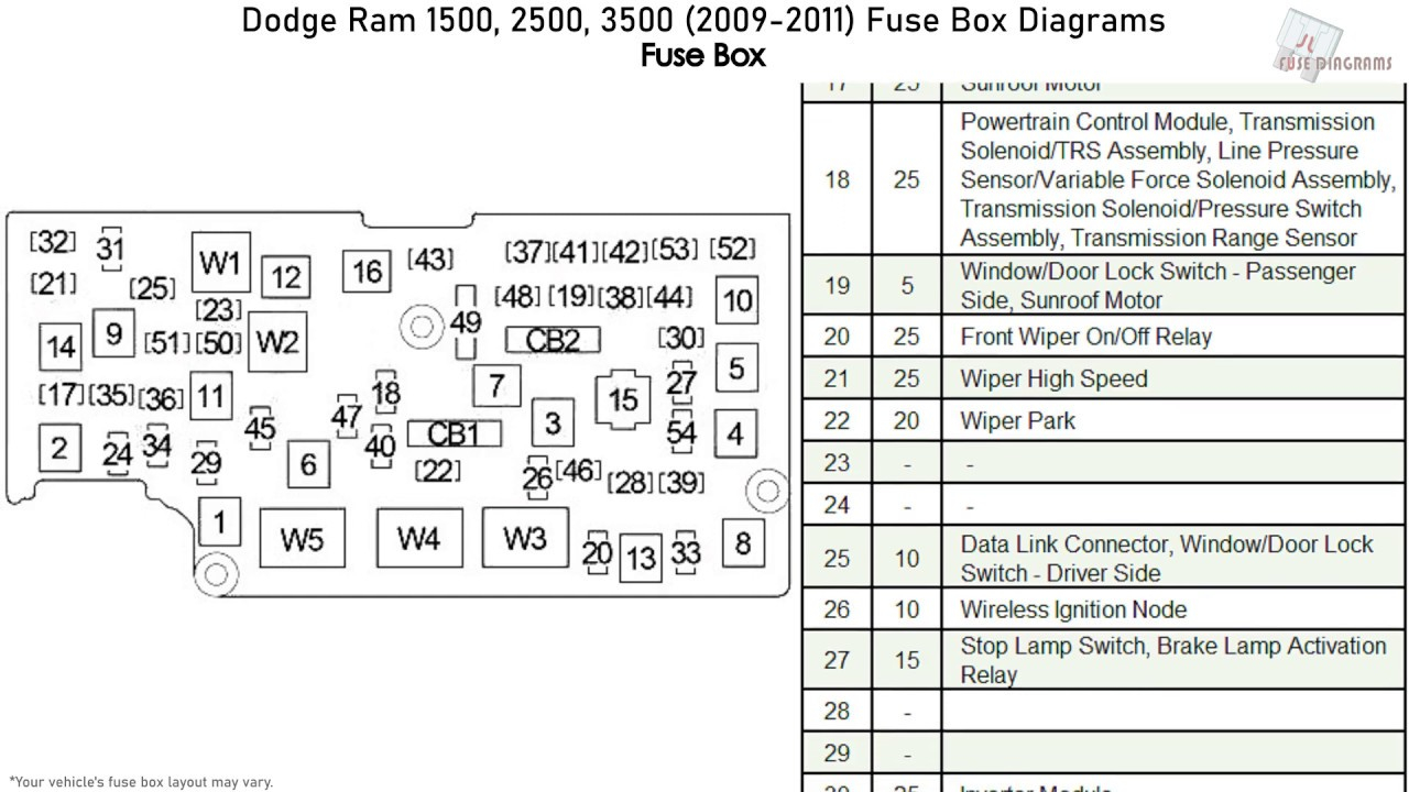
- Fuses and relays protect your electrical system from overloads and shorts, while relays regulate how power flows to different components.
Understanding the functions of these parts is essential for understanding the wiring diagram.
How to read Dodge RAM Wiring Diagrams
It can seem difficult to read wiring diagrams at first. But, it’s essential to know how to interpret them correctly to be able to recognize and fix electrical issues. The following are important points to keep in mind:
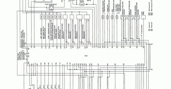
- Standard symbols and conventions used for wiring diagrams: Wiring diagrams use common symbols and conventions to show different elements and connections.
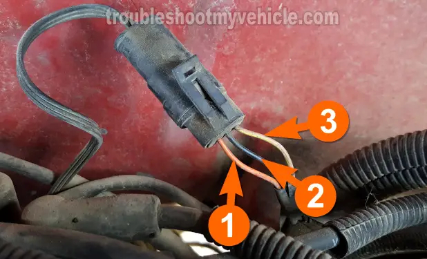
- Wire identification and color coding. Wires are color-coded to determine their purpose. Each wire is marked with an array of numbers and a letter to help determine its purpose.
- Understanding the wiring connections. Wiring Diagrams show the way that components are linked to each other and how power flows across these circuits.
Troubleshooting Electrical Issues with Dodge RAM
Even though electrical problems can be challenging If you can use the wiring diagram to identify and solve the problem can help. Here are some of the most common electrical problems that Dodge RAM faces and the steps necessary to solve them.
- Battery dead: Make sure you check your batteries, alternator, and starter.
- Blownfuses – Identify the circuit your fuse protects. Check for overloads or shorts.
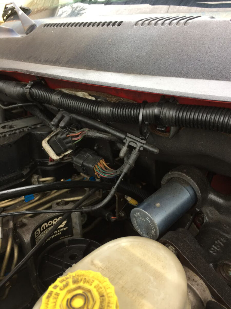
- There isn’t any power to the accessory. Make sure you check the connections to the wires, relays and fuse.
You can use the diagram of wiring to identify the circuit in question. Also, look for continuity.
Dodge RAM Wiring Harness Installation
The wiring harness upgrade on your Dodge RAM can make it more reliable and effective. These are the steps to install a new wiring harness.
- Materials and tools required The wiring harness.
- Take out the wiring Harness that was previously in use Connect the battery to the new one and label the wires.
- Install the wiring kit Then connect the wires to their components to the new harness.
Before connecting the battery be sure to check the wire harness.
VI.
In conclusion, understanding the 2010 Ram 2500 Speed Sensor Wiring Diagram is crucial for maintaining and repairing the electrical system of your vehicle. Knowing the Dodge RAM wiring diagram will help you save time and money. You can make sure that your Dodge RAM continues to run smoothly for many years by following these steps.
Gallery of 2010 Ram 2500 Speed Sensor Wiring Diagram